Sunday 16 September 2018

Putting everything Together PNR2.5 + PN Brushless ESC - Sweetness


Well I have covered most the individual parts in the past post and now its time to put everything together and you will definitely understand why all the cutting, soldering and modding is needed.


1. You will first need to solder the bridge cable for the negative and the positive terminal. I prefer to do it this way as it is neater.


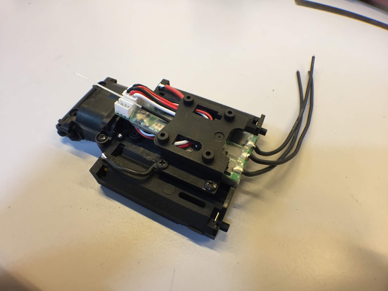
2. Next sit in the servo assembly this manner, without the switch I can hide the servo board in the switch area of the chassis.


3. Put a bit of hot glue to hold the servo board in place so that it will not move around causing tension to the wires.


4. Fit on the servo motor cover.


5. Heat shrink the PN ESC, flip it around and put a huge piece of double sided tap on the back.


6. Stick it onto the chassis. Here you can see that the CAPacitor actually sits nicely in the space where we shaved off the servo motor cover.


7. Heat shrink your receiver, flip it around and also put a huge piece of double sided tape on the reverse side.


8. Put on the front cover of the chassis and then place the receiver in this manner.
Take note of how the wires are being routed.


9. Fit on the top cover, you will realise that there is enough space for the cables as you previously shaved off part of the top deck.

Shorten the positive and negative power cable from the ESC and solder them on the chassis and you are all GOOD to go.

Happy modding GUYS :)


MODDING THE PNR ESC (Secrets Unveiled)


The chassis is ready, the servo assembly is ready and now let's get to the ESC.

There are so many ways to prep the ESC for the chassis and of cos you could just plug and play, do nothing and fit the ESC into the chassis but this is my personal preference, it looks tidy and good plus it is definitely fail save for race. You will see why ............


On the back of the ESC you will see a lot of cables, well end up I will de solder all the cables re solder them back a different way.

Lets start with the ON/OFF switch. For years all my race cars are DE SWITCHED. The reason is simple, I want to minimise any chances of failure and the ON/OFF switch might fail. Also do you really need a ON/OFF switch :p your choice.


Desolder the ON/OFF switch and just use a bit of Solder lead to short both the ON & OFF together.


Next, flip the board around and place bit solder across the last to legs on the BIG component below the button. Basically by doing so you are by-passing the BEC and allow all the power to go the board without restriction. *DO THIS ONLY IF YOU ARE RUNNING NIMH BATTERIES*


Next, remove all the cables on the reverse side. There are a couple things I am doing here so pay abit of attention.

- First, I am taking the opportunity to shorten the signal cable
- Secondly I am modding the CAPacitor so that I can get rid of long unwanted cable.


For the capacitor mod, use a tweezer and lightly pull off the heat string, you will expose the cables and you will then be able to de solder cables.


There you go- de soldered


After that you, solder the capacitor back on to the board with the cables : )

There you go.... all done. Hope its not too difficult.
:)


Servo Assembly For PNR 2.5


In the earlier post, I shared about how to prep the PNR chassis for the PN Brushless Board. Well in this tutorial let get down to the electronics and in this post we will talk about the servo assembly.


1. Servo Electronic Assembly

There are a couple of stuff you will need for the servo assembly and here are SKUs.

- 500804 PN Racing Micro Servo Board
- 500136 PN Racing Servo VR
- MZ408-2 Kyosho Servo Motor
- MZ408-1 Kyosho Servo Motor Pinion


I would recommend to start soldering the cables to to the servo board first


Follow by soldering on the servo motor as it is on the side of the board.


Next you will need to solder the cables on the VR.


Lastly the VR on to the SERVO board.


Alright, seems like the soldering is all done now lets get to the servo assembly portion.
You will again need some parts for it and the SKUs as follows:

- MZ402 Kyosho Chassis Small Part Set
- MZ405 Kyohso Servo Saver
- MZ404 Kyosho Servo Gear Set


When you put the parts together the assembled servo assembly will look like that.


There you go the servo electronics parts and the servo assembly is all done :)

While you are at this stage you are building the servo you might want to consider to soup it up alittle by changing some of these goodies from PN Racing.

MR3090 - PN Racing Delrin Servo Gears
MR3056B - PN racing Brass 4th Servo Gear

Links as follows:

http://www.kenonhobby.com/PN-Racing-Mini-Z-MR03PNW25W-Delrin-Servo-Gear-Set_p_46044.html

http://www.kenonhobby.com/PN-Racing-Mini-Z-MR03-Brass-4th-Servo-Gear_p_45963.html


Prep your PNR2.5 Chassis For The PN Brushless ESC


I have been asked multiple times how to actually prep the PNR chassis to fit the PN Brushless ESC.
So heck, let's write about it.

It is quite a lot of work but trust me it's all worth it. Moreover if it's really easy and simple then there will be alot " WORLD CHAMPS" lol.

Let's start with shaving off some parts to make space for it. I have marked out all the parts that you need to shave off in silver.


1. On the main chassis these are the areas you need to shave off.

BEFORE

AFTER


2. Next you will need to shave off some access parts on FRONT top cover and the top top deck.


BEFORE

AFTER


3. Lastly cut off a portion from the servo motor holder

BEFORE

AFTER


Well that's all for cutting. Stay tuned next for the electronic mods:)
Happy cutting guys